- 1. Design Issues There are some key design issues occur in computer networks are present in several layers Addressing Error control Flow control Multiplexing Demultiplexing Routing
- 2. Addressing Every layer needs a mechanism to identify senders and receivers.
- 3. Error control Its an important issue because physical communication circuits are not perfect. Many error detecting and error correcting codes are available. Both sending and receiving ends are must agree to use any one code.
- 4. Flow control This property leads to mechanisms for disassembling, transmitting and then reassembling messages.
- 5. Routing When there are multiple paths between source and destination, a route must be chosen.
- 6. Multiplexing and Demultiplexing These two are must for improving the n/w system.
Monday, April 21, 2014
Design issues for the layers

Network Layer Design Issues
1. Store-and-Forward Packet Switching
· The major components of the system are the carrier's equipment (routers connected by transmission lines), shown inside the shaded oval, and the customers' equipment, shown outside the oval.
· Host H1 is directly connected to one of the carrier's routers, A, by a leased line. In contrast, H2 is on a LAN with a router, F, owned and operated by the customer. This router also has a leased line to the carrier's equipment.
· We have shown F as being outside the oval because it does not belong to the carrier, but in terms of construction, software, and protocols, it is probably no different from the carrier's routers.
Figure 3-1. The environment of the network layer protocols.

· This equipment is used as follows. A host with a packet to send transmits it to the nearest router, either on its own LAN or over a point-to-point link to the carrier. The packet is stored there until it has fully arrived so the checksum can be verified.
· Then it is forwarded to the next router along the path until it reaches the destination host, where it is delivered. This mechanism is store-and-forward packet switching.
2. Services Provided to the Transport Layer
· The network layer provides services to the transport layer at the network layer/transport layer interface. An important question is what kind of services the network layer provides to the transport layer.
· The network layer services have been designed with the following goals in mind.
1. The services should be independent of the router technology.
2. The transport layer should be shielded from the number, type, and topology of the routers present.
3. The network addresses made available to the transport layer should use a uniform numbering plan, even across LANs and WANs.
Given these goals, the designers of the network layer have a lot of freedom in writing detailed specifications of the services to be offered to the transport layer. This freedom often degenerates into a raging battle between two warring factions.
The other camp argues that the subnet should provide a reliable, connection-oriented service. They claim that 100 years of successful experience with the worldwide telephone system is an excellent guide. In this view, quality of service is the dominant factor, and without connections in the subnet, quality of service is very difficult to achieve, especially for real-time traffic such as voice and video.
These two camps are best exemplified by the Internet and ATM. The Internet offers connectionless network-layer service; ATM networks offer connection-oriented network-layer service. However, it is interesting to note that as quality-of-service guarantees are becoming more and more important, the Internet is evolving.
3. Implementation of Connectionless Service
Two different organizations are possible, depending on the type of service offered. If connectionless service is offered, packets are injected into the subnet individually and routed independently of each other. No advance setup is needed.
In this context, the packets are frequently called datagrams (in analogy with telegrams) and the subnet is called a datagram subnet. If connection-oriented service is used, a path from the source router to the destination router must be established before any data packets can be sent.
This connection is called a VC (virtual circuit), in analogy with the physical circuits set up by the telephone system, and the subnet is called a virtual-circuit subnet. In this section we will examine datagram subnets; in the next one we will examine virtual-circuit subnets.
Let us now see how a datagram subnet works. Suppose that the process P1 in Fig. 3-2 has a long message for P2. It hands the message to the transport layer with instructions to deliver it to process P2 on host H2.
The transport layer code runs on H1, typically within the operating system. It prepends a transport header to the front of the message and hands the result to the network layer, probably just another procedure within the operating system.
Figure 3-2. Routing within a datagram subnet.

Let us assume that the message is four times longer than the maximum packet size, so the network layer has to break it into four packets, 1, 2, 3, and 4 and sends each of them in turn to router A using some point-to-point protocol, for example, PPP.
At this point the carrier takes over. Every router has an internal table telling it where to send packets for each possible destination. Each table entry is a pair consisting of a destination and the outgoing line to use for that destination.
Only directly-connected lines can be used. For example, in Fig. 5-2, A has only two outgoing lines—to B and C—so every incoming packet must be sent to one of these routers, even if the ultimate destination is some other router. A's initial routing table is shown in the figure under the label ''initially.''
So the checksum is added to the data unit and sends to the receiver. Final data unit is 10001010 00100011 01010000.
If the error occurred at bit 7 which is changed from 1 to 0, then receiver recalculates the same sets of bits used by the sender. By this we can identify the perfect location of error occurrence. once the bit is identified the receiver can reverse its value and correct the error.
Feed back based Flow Control
A. A Simplex Stop-and-Wait Protocol
This type of scheme is called Positive Acknowledgment with Retransmission (PAR).
B. Sliding Window Protocol
Types of Sliding Window Protocol
ii. A Protocol Using Go Back N
The problem with pipelining is if sender sending 10 packets, but the problem occurs in 8th one than it is needed to resend whole data. So the protocol called Go back N and Selective Repeat were introduced to solve this problem.In this protocol, there are two possibility at the receiver’s end, it may be with large window size or it may be with window size one.

Here the buffer size of sender and receiver is 7 and as we can see in the figure (a), the sender sends 7 frames to the receiver and starts timer. When a receiver gets the frames, it sends the ACK back to the sender and it passes the frames to the Network Layer. After doing this, receiver empties its buffer and increased sequence number and expects sequence number 7,0,1,2,3,4,5. But if the ACK is lost, the sender will not receive the ACK. So when the timer expires, the sender retransmits the original frames, 0 to 6 to the receiver. In this case the receiver accepts the frames 0 to 5 (which are duplicated) and send it to the network layer. In this case protocol fails.
1. ALOHA
Pure ALOHA ALOHA is the simplest technique in multiple accesses. Basic idea of this mechanism is a user can transmit the data whenever they want. If data is successfully transmitted then there isn’t any problem. But if collision occurs than the station will transmit again. Sender can detect the collision if it doesn’t receive the acknowledgment from the receiver.
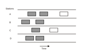
![Here packets sent at time t0 will collide with other packets sent in the time interval [t0-1, t0+1].](http://upload.wikimedia.org/wikipedia/commons/thumb/c/c2/Pure_ALOHA.svg/300px-Pure_ALOHA.svg.png)
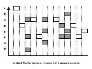
Slotted ALOHA
a. Persistent
When a station has the data to send, it first listens the channel to check if anyone else is transmitting data or not. If it senses the channel idle, station starts transmitting the data. If it senses the channel busy it waits until the channel is idle. When a station detects a channel idle, it transmits its frame with probability P. That’s why this protocol is called p-persistent CSMA. This protocol applies to slotted channels. When a station finds the channel idle, if it transmits the fame with probability 1, that this protocol is known as 1 -persistent. 1 -persistent protocol is the most aggressive protocol.
Non persistent CSMA is less aggressive compared to P persistent protocol. In this protocol, before sending the data, the station senses the channel and if the channel is idle it starts transmitting the data. But if the channel is busy, the station does not continuously sense it but instead of that it waits for random amount of time and repeats the algorithm. Here the algorithm leads to better channel utilization but also results in longer delay compared to 1 –persistent.
CSMA/CD
Carrier Sense Multiple Access/Collision Detection a technique for multiple access protocols. If no transmission is taking place at the time, the particular station can transmit. If two stations attempt to transmit simultaneously, this causes a collision, which is detected by all participating stations. After a random time interval, the stations that collided attempt to transmit again. If another collision occurs, the time intervals from which the random waiting time is selected are increased step by step. This is known as exponential back off.
Exponential back off Algorithm
CSMA/CA
CSMA/CA is Carrier Sense Multiple Access/Collision Avoidance. In this multiple access protocol, station senses the medium before transmitting the frame. This protocol has been developed to improve the performance of CSMA. CASMA/CA is used in 802.11 based wireless LANs. In wireless LANs it is not possible to listen to the medium while transmitting. So collision detection is not possible.

1. Hidden Station Problem (Figure a)
When a station sends the packet to another station/receiver, some other station which is not in sender’s range may start sending the packet to the same receiver. That will create collision of packets. This problem is explained more specifically below.

2. Exposed Station Problem (Figure b)
When A is sending the packet, C will also hear. So if station wants to send the packet D, still it won’t send. This will reduce the efficiency of the protocol. This problem is called Exposed Station problem.
To deal with these problems 802.11 supports two kinds of operations.
DCF
DCF does not use and central control. It uses CSMA/CA protocol. It uses physical channel sensing and virtual channel sensing. Here when a station wants to send packets, first it senses the channel. If the channel is idle, immediately starts transmitting. While transmitting, it does not sense the channel, but it emits its entire frame. This frame can be destroyed at the receiver side if receiver has started transmitting. In this case, if collision occurs, the colliding stations wait for random amount of time using the binary exponential back off algorithm and tries again letter.


PCF mechanism uses base station to control all activity in its cell. Base station polls the other station asking them if they have any frame to send. In PCF, as it is centralized, no collision will occur. In polling mechanism, the base station broadcasts a beacon frame periodically (10 to 100 times per second). Beacon frame contains system parameters such as hopping sequences, dwell times, clock synchronization etc. It also invites new station to sign up. All signed up stations are guaranteed to get a certain fraction of the bandwidth. So in PCF quality of service is guaranteed.
All implementations must support DCF but PCF is optional. PCF and DCF can coexist within one sell. Distributed control and Centralized control, both can operate at the same time using interframe time interval. There are four interval defined. This four intervals are shown in the figure given below.


· Host H1 is directly connected to one of the carrier's routers, A, by a leased line. In contrast, H2 is on a LAN with a router, F, owned and operated by the customer. This router also has a leased line to the carrier's equipment.
· We have shown F as being outside the oval because it does not belong to the carrier, but in terms of construction, software, and protocols, it is probably no different from the carrier's routers.
Figure 3-1. The environment of the network layer protocols.
· This equipment is used as follows. A host with a packet to send transmits it to the nearest router, either on its own LAN or over a point-to-point link to the carrier. The packet is stored there until it has fully arrived so the checksum can be verified.
· Then it is forwarded to the next router along the path until it reaches the destination host, where it is delivered. This mechanism is store-and-forward packet switching.
2. Services Provided to the Transport Layer
· The network layer provides services to the transport layer at the network layer/transport layer interface. An important question is what kind of services the network layer provides to the transport layer.
· The network layer services have been designed with the following goals in mind.
1. The services should be independent of the router technology.
2. The transport layer should be shielded from the number, type, and topology of the routers present.
3. The network addresses made available to the transport layer should use a uniform numbering plan, even across LANs and WANs.
Given these goals, the designers of the network layer have a lot of freedom in writing detailed specifications of the services to be offered to the transport layer. This freedom often degenerates into a raging battle between two warring factions.
The other camp argues that the subnet should provide a reliable, connection-oriented service. They claim that 100 years of successful experience with the worldwide telephone system is an excellent guide. In this view, quality of service is the dominant factor, and without connections in the subnet, quality of service is very difficult to achieve, especially for real-time traffic such as voice and video.
These two camps are best exemplified by the Internet and ATM. The Internet offers connectionless network-layer service; ATM networks offer connection-oriented network-layer service. However, it is interesting to note that as quality-of-service guarantees are becoming more and more important, the Internet is evolving.
3. Implementation of Connectionless Service
Two different organizations are possible, depending on the type of service offered. If connectionless service is offered, packets are injected into the subnet individually and routed independently of each other. No advance setup is needed.
In this context, the packets are frequently called datagrams (in analogy with telegrams) and the subnet is called a datagram subnet. If connection-oriented service is used, a path from the source router to the destination router must be established before any data packets can be sent.
This connection is called a VC (virtual circuit), in analogy with the physical circuits set up by the telephone system, and the subnet is called a virtual-circuit subnet. In this section we will examine datagram subnets; in the next one we will examine virtual-circuit subnets.
Let us now see how a datagram subnet works. Suppose that the process P1 in Fig. 3-2 has a long message for P2. It hands the message to the transport layer with instructions to deliver it to process P2 on host H2.
The transport layer code runs on H1, typically within the operating system. It prepends a transport header to the front of the message and hands the result to the network layer, probably just another procedure within the operating system.
Figure 3-2. Routing within a datagram subnet.
Let us assume that the message is four times longer than the maximum packet size, so the network layer has to break it into four packets, 1, 2, 3, and 4 and sends each of them in turn to router A using some point-to-point protocol, for example, PPP.
At this point the carrier takes over. Every router has an internal table telling it where to send packets for each possible destination. Each table entry is a pair consisting of a destination and the outgoing line to use for that destination.
Only directly-connected lines can be used. For example, in Fig. 5-2, A has only two outgoing lines—to B and C—so every incoming packet must be sent to one of these routers, even if the ultimate destination is some other router. A's initial routing table is shown in the figure under the label ''initially.''
However, something different happened to packet 4. When it got to A it was sent to router B, even though it is also destined for F. For some reason, A decided to send packet 4 via a different route than that of the first three.
Perhaps it learned of a traffic jam somewhere along the ACE path and updated its routing table, as shown under the label ''later.'' The algorithm that manages the tables and makes the routing decisions is called the routing algorithm.
4. Implementation of Connection-Oriented Service
For connection-oriented service, we need a virtual-circuit subnet. The idea behind virtual circuits is to avoid having to choose a new route for every packet sent, as in Fig. 3-2.
Instead, when a connection is established, a route from the source machine to the destination machine is chosen as part of the connection setup and stored in tables inside the routers. That route is used for all traffic flowing over the connection, exactly the same way that the telephone system works.
When the connection is released, the virtual circuit is also terminated. With connection-oriented service, each packet carries an identifier telling which virtual circuit it belongs to. As an example, consider the situation of Fig. 3-3. Here, host H1 has established connection 1 with host H2.
It is remembered as the first entry in each of the routing tables. The first line of A's table says that if a packet bearing connection identifier 1 comes in from H1, it is to be sent to router C and given connection identifier 1. Similarly, the first entry at C routes the packet to E, also with connection identifier 1.
Figure 3-3. Routing within a virtual-circuit subnet.

Now let us consider what happens if H3 also wants to establish a connection to H2. It chooses connection identifier 1 and tells the subnet to establish the virtual circuit. This leads to the second row in the tables.
Note that we have a conflict here because although A can easily distinguish connection 1 packets from H1 from connection 1 packets from H3, C cannot do this. For this reason, A assigns a different connection identifier to the outgoing traffic for the second connection.
Avoiding conflicts of this kind is why routers need the ability to replace connection identifiers in outgoing packets. In some contexts, this is called label switching.
5. Comparison of Virtual-Circuit and Datagram Subnets
Both virtual circuits and datagrams have their supporters and their detractors. We will now attempt to summarize the arguments both ways. The major issues are listed in Fig. 3-4, although purists could probably find a counterexample for everything in the figure.
Figure 3-4. Comparison of datagram and virtual-circuit subnets.

Inside the subnet, several trade-offs exist between virtual circuits and datagrams. One trade-off is between router memory space and bandwidth. Virtual circuits allow packets to contain circuit numbers instead of full destination addresses.
If the packets tend to be fairly short, a full destination address in every packet may represent a significant amount of overhead and hence, wasted bandwidth. The price paid for using virtual circuits internally is the table space within the routers.
Depending upon the relative cost of communication circuits versus router memory, one or the other may be cheaper. Another trade-off is setup time versus address parsing time. Using virtual circuits requires a setup phase, which takes time and consumes resources.
However, figuring out what to do with a data packet in a virtual-circuit subnet is easy: the router just uses the circuit number to index into a table to find out where the packet goes. In a datagram subnet, a more complicated lookup procedure is required to locate the entry for the destination.
For transaction processing systems (e.g., stores calling up to verify credit card purchases), the overhead required to set up and clear a virtual circuit may easily dwarf the use of the circuit. If the majority of the traffic is expected to be of this kind, the use of virtual circuits inside the subnet makes little sense.
On the other hand, permanent virtual circuits, which are set up manually and last for months or years, may be useful here. Virtual circuits also have a vulnerability problem. If a router crashes and loses its memory, even if it comes back up a second later, all the virtual circuits passing through it will have to be aborted.
In contrast, if a datagram router goes down, only those users whose packets were queued in the router at the time will suffer, and maybe not even all those, depending upon whether they have already been acknowledged.
The loss of a communication line is fatal to virtual circuits using it but can be easily compensated for if datagrams are used. Datagrams also allow the routers to balance the traffic throughout the subnet, since routes can be changed partway through a long sequence of packet transmissions..
Perhaps it learned of a traffic jam somewhere along the ACE path and updated its routing table, as shown under the label ''later.'' The algorithm that manages the tables and makes the routing decisions is called the routing algorithm.
4. Implementation of Connection-Oriented Service
For connection-oriented service, we need a virtual-circuit subnet. The idea behind virtual circuits is to avoid having to choose a new route for every packet sent, as in Fig. 3-2.
Instead, when a connection is established, a route from the source machine to the destination machine is chosen as part of the connection setup and stored in tables inside the routers. That route is used for all traffic flowing over the connection, exactly the same way that the telephone system works.
When the connection is released, the virtual circuit is also terminated. With connection-oriented service, each packet carries an identifier telling which virtual circuit it belongs to. As an example, consider the situation of Fig. 3-3. Here, host H1 has established connection 1 with host H2.
It is remembered as the first entry in each of the routing tables. The first line of A's table says that if a packet bearing connection identifier 1 comes in from H1, it is to be sent to router C and given connection identifier 1. Similarly, the first entry at C routes the packet to E, also with connection identifier 1.
Figure 3-3. Routing within a virtual-circuit subnet.
Now let us consider what happens if H3 also wants to establish a connection to H2. It chooses connection identifier 1 and tells the subnet to establish the virtual circuit. This leads to the second row in the tables.
Note that we have a conflict here because although A can easily distinguish connection 1 packets from H1 from connection 1 packets from H3, C cannot do this. For this reason, A assigns a different connection identifier to the outgoing traffic for the second connection.
Avoiding conflicts of this kind is why routers need the ability to replace connection identifiers in outgoing packets. In some contexts, this is called label switching.
5. Comparison of Virtual-Circuit and Datagram Subnets
Both virtual circuits and datagrams have their supporters and their detractors. We will now attempt to summarize the arguments both ways. The major issues are listed in Fig. 3-4, although purists could probably find a counterexample for everything in the figure.
Figure 3-4. Comparison of datagram and virtual-circuit subnets.
Inside the subnet, several trade-offs exist between virtual circuits and datagrams. One trade-off is between router memory space and bandwidth. Virtual circuits allow packets to contain circuit numbers instead of full destination addresses.
If the packets tend to be fairly short, a full destination address in every packet may represent a significant amount of overhead and hence, wasted bandwidth. The price paid for using virtual circuits internally is the table space within the routers.
Depending upon the relative cost of communication circuits versus router memory, one or the other may be cheaper. Another trade-off is setup time versus address parsing time. Using virtual circuits requires a setup phase, which takes time and consumes resources.
However, figuring out what to do with a data packet in a virtual-circuit subnet is easy: the router just uses the circuit number to index into a table to find out where the packet goes. In a datagram subnet, a more complicated lookup procedure is required to locate the entry for the destination.
For transaction processing systems (e.g., stores calling up to verify credit card purchases), the overhead required to set up and clear a virtual circuit may easily dwarf the use of the circuit. If the majority of the traffic is expected to be of this kind, the use of virtual circuits inside the subnet makes little sense.
On the other hand, permanent virtual circuits, which are set up manually and last for months or years, may be useful here. Virtual circuits also have a vulnerability problem. If a router crashes and loses its memory, even if it comes back up a second later, all the virtual circuits passing through it will have to be aborted.
In contrast, if a datagram router goes down, only those users whose packets were queued in the router at the time will suffer, and maybe not even all those, depending upon whether they have already been acknowledged.
The loss of a communication line is fatal to virtual circuits using it but can be easily compensated for if datagrams are used. Datagrams also allow the routers to balance the traffic throughout the subnet, since routes can be changed partway through a long sequence of packet transmissions..
Communication Networks/Error Control, Flow Control, MAC..
Error Control
Network is responsible for transmission of data from one device to another device. The end to end transfer of data from a transmitting application to a receiving application involves many steps, each subject to error. With the error control process, we can be confident that the transmitted and received data are identical. Data can be corrupted during transmission. For reliable communication, error must be detected and corrected.
Error control is the process of detecting and correcting both the bit level and packet level errors.
Types of Errors
Single Bit Error
The term single bit error means that only one bit of the data unit was changed from 1 to 0 and 0 to 1.
Burst Error
In term burst error means that two or more bits in the data unit were changed. Burst error is also called packet level error, where errors like packet loss, duplication, reordering.
Error Detection
Error detection is the process of detecting the error during the transmission between the sender and the receiver.
Types of error detection
- Parity checking
- Cyclic Redundancy Check (CRC)
- Checksum
Redundancy
Redundancy allows a receiver to check whether received data was corrupted during transmission. So that he can request a retransmission. Redundancy is the concept of using extra bits for use in error detection. As shown in the figure sender adds redundant bits (R) to the data unit and sends to receiver, when receiver gets bits stream and passes through checking function. If no error then data portion of the data unit is accepted and redundant bits are discarded. otherwise asks for the retransmission.
Parity checking
Parity adds a single bit that indicates whether the number of 1 bits in the preceding data is even or odd. If a single bit is changed in transmission, the message will change parity and the error can be detected at this point. Parity checking is not very robust, since if the number of bits changed is even, the check bit will be invalid and the error will not be detected.
- Single bit parity
- Two dimension parity
Moreover, parity does not indicate which bit contained the error, even when it can detect it. The data must be discarded entirely, and re-transmitted from scratch. On a noisy transmission medium a successful transmission could take a long time, or even never occur. Parity does have the advantage, however, that it's about the best possible code that uses only a single bit of space.
Cyclic Redundancy Check
CRC is a very efficient redundancy checking technique. It is based on binary division of the data unit, the remainder of which (CRC) is added to the data unit and sent to the receiver. The Receiver divides data unit by the same divisor. If the remainder is zero then data unit is accepted and passed up the protocol stack, otherwise it is considered as having been corrupted in transit, and the packet is dropped.
Sequential steps in CRC are as follows.
Sender follows following steps.
- Data unit is composite by number of 0s, which is one less than the divisor.
- Then it is divided by the predefined divisor using binary division technique. The remainder is called CRC. CRC is appended to the data unit and is sent to the receiver.
Receiver follows following steps.
- When data unit arrives followed by the CRC it is divided by the same divisor which was used to find the CRC (remainder).
- If the remainder result in this division process is zero then it is error free data, otherwise it is corrupted.
Diagram shows how to CRC process works.
[a] sender CRC generator [b] receiver CRC checker
Checksum
Check sum is the third method for error detection mechanism. Checksum is used in the upper layers, while Parity checking and CRC is used in the physical layer. Checksum is also on the concept of redundancy.
In the checksum mechanism two operations to perform.
Checksum generator
Sender uses checksum generator mechanism. First data unit is divided into equal segments of n bits. Then all segments are added together using 1’s complement. Then it complements ones again. It becomes Checksum and sends along with data unit.
Exp:
If 16 bits 10001010 00100011 is to be sent to receiver.
So the checksum is added to the data unit and sends to the receiver. Final data unit is 10001010 00100011 01010000.
Checksum checker
Receiver receives the data unit and divides into segments of equal size of segments. All segments are added using 1’s complement. The result is completed once again. If the result is zero, data will be accepted, otherwise rejected.
Exp:
The final data is nonzero then it is rejected.
Error Correction
This type of error control allows a receiver to reconstruct the original information when it has been corrupted during transmission.
Hamming Code
It is a single bit error correction method using redundant bits.
In this method redundant bits are included with the original data. Now, the bits are arranged such that different incorrect bits produce different error results and the corrupt bit can be identified. Once the bit is identified, the receiver can reverse its value and correct the error. Hamming code can be applied to any length of data unit and uses the relationships between the data and the redundancy bits.
Algorithm:
- Parity bits are positions at the power of two (2 r).
- Rest of the positions is filled by original data.
- Each parity bit will take care of its bits in the code.
- Final code will sends to the receiver.
In the above example we calculates the even parities for the various bit combinations. the value for the each combination is the value for the corresponding r(redundancy)bit. r1 will take care of bit 1,3,5,7,9,11. and it is set based on the sum of even parity bit. the same method for rest of the parity bits.
If the error occurred at bit 7 which is changed from 1 to 0, then receiver recalculates the same sets of bits used by the sender. By this we can identify the perfect location of error occurrence. once the bit is identified the receiver can reverse its value and correct the error.
Flow Control
Flow Control is one important design issue for the Data Link Layer that controls the flow of data between sender and receiver.
In Communication, there is communication medium between sender and receiver. When Sender sends data to receiver than there can be problem in below case :
1) Sender sends data at higher rate and receive is too sluggish to support that data rate.
To solve the above problem, FLOW CONTROL is introduced in Data Link Layer. It also works on several higher layers. The main concept of Flow Control is to introduceEFFICIENCY in Computer Networks.
Approaches of Flow Control
- Feed back based Flow Control
- Rate based Flow Control
Feed back based Flow Control is used in Data Link Layer and Rate based Flow Control is used in Network Layer.
Feed back based Flow Control
In Feed back based Flow Control, Until sender receives feedback from the receiver, it will not send next data.
Types of Feedback based Flow Control
A. Stop-and-Wait Protocol
B. Sliding Window Protocol
- A One-Bit Sliding Window Protocol
- A Protocol Using Go Back N
- A Protocol Using Selective Repeat
A. A Simplex Stop-and-Wait Protocol
In this Protocol we have taken the following assumptions:
- It provides unidirectional flow of data from sender to receiver.
- The Communication channel is assumed to be error free.
In this Protocol the Sender simply sends data and waits for the acknowledgment from Receiver. That's why it is called Stop-and-Wait Protocol.
This type is not so much efficient, but it is simplest way of Flow Control.
In this scheme we take Communication Channel error free, but if the Channel has some errors than receiver is not able to get the correct data from sender so it will not possible for sender to send the next data (because it will not get acknowledge from receiver). So it will end the communication, to solve this problem there are two new concepts were introduced.
- TIMER, if sender was not able to get acknowledgment in the particular time than, it sends the buffered data once again to receiver. When sender starts to send the data, it starts timer.
- SEQUENCE NUMBER, from this the sender sends the data with the specific sequence number so after receiving the data, receiver sends the data with that sequence number, and here at sender side it also expect the acknowledgment of the same sequence number.
This type of scheme is called Positive Acknowledgment with Retransmission (PAR).
B. Sliding Window Protocol
Problems Stop –wait protocol In the last protocols sender must wait for either positive acknowledgment from receiver or for time out to send the next frame to receiver. So if the sender is ready to send the new data, it can not send. Sender is dependent on the receiver. Previous protocols have only the flow of one sided, means only sender sends the data and receiver just acknowledge it, so the twice bandwidth is used.
To solve the above problems the Sliding Window Protocol was introduce.
In this, the sender and receiver both use buffer, it’s of same size, so there is no necessary to wait for the sender to send the second data, it can send one after one without wait of the receiver’s acknowledgment.
And it also solve the problem of uses of more bandwidth, because in this scheme both sender and receiver uses the channel to send the data and receiver just send the acknowledge with the data which it want to send to sender, so there is no special bandwidth is used for acknowledgment, so the bandwidth is saved, and this whole process is called PIGGYBACKING.
Types of Sliding Window Protocol
i. A One-Bit Sliding Window Protocol
ii. A Protocol Using Go Back N
iii. A Protocol Using Selective Repeat
i. A One-Bit Sliding Window Protocol
This protocol has buffer size of one bit, so only possibility for sender and receiver to send and receive packet is only 0 and 1. This protocol includes Sequence, Acknowledge, and Packet number.It uses full duplex channel so there is two possibilities:
- Sender first start sending the data and receiver start sending data after it receive the data.
- Receiver and sender both start sending packets simultaneously,
First case is simple and works perfectly, but there will be an error in the second one. That error can be like duplication of the packet, without any transmission error.
ii. A Protocol Using Go Back N
The problem with pipelining is if sender sending 10 packets, but the problem occurs in 8th one than it is needed to resend whole data. So the protocol called Go back N and Selective Repeat were introduced to solve this problem.In this protocol, there are two possibility at the receiver’s end, it may be with large window size or it may be with window size one.

The window size at the receiver end may be large or only of one. In the case of window size is one at the receiver, as we can see in the figure (a), if sender wants to send the packet from one to ten but suppose it has error in 2nd packet, so sender will start from zero, one, two, etc. here we assume that sender has the time out interval with 8. So the time out will occur after the 8 packets, up to that it will not wait for the acknowledgment. In this case at the receiver side the 2nd packet come with error, and other up to 8 were discarded by receiver. So in this case the loss of data is more.
Whether in the other case with the large window size at receiver end as we can see in the figure (b) if the 2nd packet comes with error than the receiver will accept the 3rd packet but it sends NAK of 2 to the sender and buffer the 3rd packet. Receiver do the same thing in 4th and 5th packet. When the sender receiver the NAK of 2nd packet it immediately send the 2nd packet to the receiver. After receiving the 2nd packet, receiver send the ACK of 5th one as saying that it received up to 5 packet. So there is no need to resend 3rd , 4th and 5th packet again, they are buffered in the receiver side.
iii. A Protocol Using Selective Repeat
Protocol using Go back N is good when the errors are rare, but if the line is poor, it wastes a lot of bandwidth on retransmitted frames. So to provide reliability, Selective repeat protocol was introduced. In this protocol sender starts it's window size with 0 and grows to some predefined maximum number. Receiver's window size is fixed and equal to the maximum number of sender's window size. The receiver has a buffer reserved for each sequence number within its fixed window.
Whenever a frame arrives, its sequence number is checked by the function to see if it falls within the window, if so and if it has not already been received, it is accepted and stored. This action is taken whether it is not expected by the network layer.
Here the buffer size of sender and receiver is 7 and as we can see in the figure (a), the sender sends 7 frames to the receiver and starts timer. When a receiver gets the frames, it sends the ACK back to the sender and it passes the frames to the Network Layer. After doing this, receiver empties its buffer and increased sequence number and expects sequence number 7,0,1,2,3,4,5. But if the ACK is lost, the sender will not receive the ACK. So when the timer expires, the sender retransmits the original frames, 0 to 6 to the receiver. In this case the receiver accepts the frames 0 to 5 (which are duplicated) and send it to the network layer. In this case protocol fails.
To solve the problem of duplication, the buffer size of sender and receiver should be (MAX SEQ + 1)/2 that is half of the frames to be send. As we can see in fig(c ), the sender sends the frames from 0 to 3 as it's window size is 4. Receiver accepts the frames and sends acknowledgment to the sender and passes the frames to the network layer and increases the expected sequence number from 4 to 7. If the ACK is lost than sender will send 0 to 3 to receiver again but receiver is expecting to 4 to 7, so it will not accept it. So this way the problem of duplication is solved.
MAC[edit]
The data link layer is divided into two sublayers: The Media Access Control (MAC) layer and the Logical Link Control (LLC) layer. The MAC sublayer controls how a computer on the network gains access to the data and permission to transmit it. The LLC layer controls frame synchronization, flow control and error checking.
Mac Layer is one of the sublayers that makeup the datalink layer of the OSI reference Model.
MAC layer is responsible for moving packets from one Network Interface card NIC to another across the shared channel
The MAC sublayer uses MAC protocols to ensure that signals sent from different stations across the same channel don't collide.
Different protocols are used for different shared networks, such as Ethernets, Token Rings, Token Buses, and WANs.
1. ALOHA
ALOHA is a simple communication scheme in which each source in a network sends its data whenever there is a frame to send without checking to see if any other station is active. After sending the frame each station waits for implicit or explicit acknowledgment. If the frame successfully reaches the destination, next frame is sent. And if the frame fails to be received at the destination it is sent again.
Pure ALOHA ALOHA is the simplest technique in multiple accesses. Basic idea of this mechanism is a user can transmit the data whenever they want. If data is successfully transmitted then there isn’t any problem. But if collision occurs than the station will transmit again. Sender can detect the collision if it doesn’t receive the acknowledgment from the receiver.

![Here packets sent at time t0 will collide with other packets sent in the time interval [t0-1, t0+1].](http://commons.wikimedia.org/wiki/File:Pure_ALOHA.svg)
In ALOHA Collision probability is quite high. ALOHA is suitable for the network where there is a less traffic. Theoretically it is proved that maximum throughput for ALOHA is 18%.
                     P (success by given node) = P(node transmits) . P(no other node transmits in [t0-1,t0] . P(no other node transmits in [t0,t0 +1]
                                               = p . (1-p)N-1 . (1-p)N-1
                 P (success by any of N nodes) = N . p . (1-p) N-1 . (1-p)N-1
                                               … Choosing optimum p as N -->  infinity...
                                               = 1 / (2e) = .18
                                               =18%
Slotted ALOHA
In ALOHA a newly emitted packet can collide with a packet in progress. If all packets are of the same length and take L time units to transmit, then it is easy to see that a packet collides with any other packet transmitted in a time window of length 2L. If this time window is decreased somehow, than number of collisions decreases and the throughput increase. This mechanism is used in slotted ALOHA or S-ALOHA. Time is divided into equal slots of Length L. When a station wants to send a packet it will wait till the beginning of the next time slot.
Advantages of slotted ALOHA:
- single active node can continuously transmit at full rate of channel
- highly decentralized: only slots in nodes need to be in sync
- simple
Disadvantages of slotted ALOHA:
- collisions, wasting slots
- idle slots
- clock synchronization
Efficiency of Slotted ALOHA:
- Suppose there are N nodes with many frames to send. The probability of sending frames of each node into the slot is p.
- Probability that node 1 has a success in getting the slot is p.(1-p)N-1
- Probability that every node has a success is N.p.(1-p)N-1
- For max efficiency with N nodes, find p* that maximizes Np(1-p)N-1
- For many nodes, take limit of Np*(1-p*)N-1 as N goes to infinity, gives 1/e = .37
The clear advantage of slotted ALOHA is higher throughput. But introduces complexity in the stations and bandwidth overhead because of the need for time synchronization.

2. Carrier Sense Multiple Access protocols (CSMA)
With slotted ALOHA, the best channel utilization that can be achieved is 1/e. Several protocols are developed for improving the performance.
Protocols that listen for a carrier and act accordingly are called carrier sense protocols. Carrier sensing allows the station to detect whether the medium is currently being used. Schemes that use a carrier sense circuits are classed together as carrier sense multiple access or CSMA schemes. There are two variants of CSMA. CSMA/CD and CSMA/CA
The simplest CSMA scheme is for a station to sense the medium, sending packets immediately if the medium is idle. If the station waits for the medium to become idle it is called persistent otherwise it is called non persistent.
a. Persistent
When a station has the data to send, it first listens the channel to check if anyone else is transmitting data or not. If it senses the channel idle, station starts transmitting the data. If it senses the channel busy it waits until the channel is idle. When a station detects a channel idle, it transmits its frame with probability P. That’s why this protocol is called p-persistent CSMA. This protocol applies to slotted channels. When a station finds the channel idle, if it transmits the fame with probability 1, that this protocol is known as 1 -persistent. 1 -persistent protocol is the most aggressive protocol.
b. Non-Persistent
Non persistent CSMA is less aggressive compared to P persistent protocol. In this protocol, before sending the data, the station senses the channel and if the channel is idle it starts transmitting the data. But if the channel is busy, the station does not continuously sense it but instead of that it waits for random amount of time and repeats the algorithm. Here the algorithm leads to better channel utilization but also results in longer delay compared to 1 –persistent.
CSMA/CD
Carrier Sense Multiple Access/Collision Detection a technique for multiple access protocols. If no transmission is taking place at the time, the particular station can transmit. If two stations attempt to transmit simultaneously, this causes a collision, which is detected by all participating stations. After a random time interval, the stations that collided attempt to transmit again. If another collision occurs, the time intervals from which the random waiting time is selected are increased step by step. This is known as exponential back off.
Exponential back off Algorithm
- Adaptor gets datagram and creates frame
- If adapter senses channel idle (9.6 microsecond), it starts to transmit frame. If it senses channel busy, waits until channel idle and then transmits
- If adapter transmits entire frame without detecting another transmission, the adapter is done with frame!
- If adapter detects another transmission while transmitting, aborts and sends jam signal
- After aborting, adapter enters exponential backoff: after the mth collision, adapter chooses a K at random from {0,1,2,…,2m-1}. Adapter waits K*512 bit times (i.e. slot) and returns to Step 2
- After 10th retry, random number stops at 1023. After 16th retry, system stops retry.
CSMA/CA
CSMA/CA is Carrier Sense Multiple Access/Collision Avoidance. In this multiple access protocol, station senses the medium before transmitting the frame. This protocol has been developed to improve the performance of CSMA. CASMA/CA is used in 802.11 based wireless LANs. In wireless LANs it is not possible to listen to the medium while transmitting. So collision detection is not possible.
In CSMA/CA, when the station detects collision, it waits for the random amount of time. Then before transmitting the packet, it listens to the medium. If station senses the medium idle, it starts transmitting the packet. If it detects the medium busy, it waits for the channel to become idle.

When A wants to transmit a packet to B, first it sends RTS (Request to Send) packet of 30 bytes to B with length L. If B is idle, it sends its response to A with CTS packet (Clear to Send). Here whoever listens to the CTS packet remains silent for duration of L. When A receives CTS, it sends data of L length to B.
There are several issues in this protocol
- Hidden Station Problem
- Exposed Station Problem
1. Hidden Station Problem (Figure a)
When a station sends the packet to another station/receiver, some other station which is not in sender’s range may start sending the packet to the same receiver. That will create collision of packets. This problem is explained more specifically below.

Suppose A is sending a packet to B. Now at the same time D also wants to send the packet to B. Here D does not hear A. So D will also send its packets to B. SO collision will occur.
2. Exposed Station Problem (Figure b)
When A is sending the packet, C will also hear. So if station wants to send the packet D, still it won’t send. This will reduce the efficiency of the protocol. This problem is called Exposed Station problem.
To deal with these problems 802.11 supports two kinds of operations.
- DCF (Distributed Coordination Function)
- PCF (Point Coordinated Function)
DCF
DCF does not use and central control. It uses CSMA/CA protocol. It uses physical channel sensing and virtual channel sensing. Here when a station wants to send packets, first it senses the channel. If the channel is idle, immediately starts transmitting. While transmitting, it does not sense the channel, but it emits its entire frame. This frame can be destroyed at the receiver side if receiver has started transmitting. In this case, if collision occurs, the colliding stations wait for random amount of time using the binary exponential back off algorithm and tries again letter.
Virtual sensing is explained in the figure given below.

Here, A wants to send a packet to B. Station C is within A’s Range. Station D is within B’s range but not A’s range. When A wants to send a packet to B, first it sends the RTS (30 bytes) packet to B, asking for the permission to send the packet. In the response, if B wants to grant the permission, it will send the CTS packet to A giving permission to A for sending the packet. When A receives its frame it starts ACK timer. When the frame is successfully transmitted, B sends ACK frame. Here if A’s ACK time expires before receiving B’s ACK frame, the whole process will run again. Here for the stations C and D, when station A sends RTS to station B, RTS will also be received by C. By viewing the information provided in RTS, C will realize that some on is sending the packet and also how long the sequence will take, including the final ACK. So C will assert a kind of virtual channel busy by itself, (indicated by NAV (network Allocation Vector) in the figure above).remain silent for the particular amount of time. Station D will not receive RTS, but it will receive CTS from B. So B will also assert the NAV signal for itself.
If the channel is too noisy, when A send the frame to B and a frame is too large then there are more possibilities of the frame getting damaged and so the frame will be retransmitted. C and D, both stations will also remain silent until the whole frame is transmitted successfully. To deal with this problem of noisy channels, 802.11 allows the frame to be fragmented into smaller fragments. Once the channel has been acquired using CTS and RTS, multiple segments can be sent in a row. Sequence of segments is called a fragmentation burst. Fragmentation increases the throughput by restricting retransmissions to the bad fragments rather than the entire frame.

PCF
PCF mechanism uses base station to control all activity in its cell. Base station polls the other station asking them if they have any frame to send. In PCF, as it is centralized, no collision will occur. In polling mechanism, the base station broadcasts a beacon frame periodically (10 to 100 times per second). Beacon frame contains system parameters such as hopping sequences, dwell times, clock synchronization etc. It also invites new station to sign up. All signed up stations are guaranteed to get a certain fraction of the bandwidth. So in PCF quality of service is guaranteed.
All implementations must support DCF but PCF is optional. PCF and DCF can coexist within one sell. Distributed control and Centralized control, both can operate at the same time using interframe time interval. There are four interval defined. This four intervals are shown in the figure given below.

- SIFS - Short InterFrame Spacing
- PIFS – PCF InterFrame Spacing
- DIFS – DCF InterFrame Spacing
- EIFS – Extended Inter Frame Spacing
More about this has been explained in section 3 of Data Link Layer.
Taking Turns MAC protocols
Polling
In Polling, master node invites slave nodes to transmit in nodes. Single point of failure (master node failure), polling overhead, latency are the concerns in polling.
Bit map Reservation
In Bit map reservation, stations reserves contention slots in advance. Polling overhead and latency are the concerns in this protocol.

Token Passing
In this protocol, token is passed from one node to next sequentially. Single point of failure (token), token overhead, latency are the concerns in token passing.

Problems[edit]
- Explain hidden station and exposed station problem.
- Explain Binary Exponential Backoff Algorithm.
- Two CSMA/C stations are trying to transmit long files. After each frame is sent, they contend for the channel using binary exponential backoff algorithm. What is the probability that the connection ends on round k?
- In CRC , if th data unit is 101100 the divisor 1010 and the reminder is 110 what is the dividend at the receiver?
Network Software: The Protocol Hierarchy
The first computer networks were designed with the hardware as the main concern and the software as an afterthought.This strategy no longer works. Network software is now highly structured.
To reduce their design complexity, most networks are organized as a series or hierarchy of layers or levels.
The number of layers, the name of each layer, the contents of each layer, and the function of each layer differ from network to network.
Layer n on one machine communicates with layer n on another machine on the network using an some rules known as the layer n protocol.
A protocol is an agreement between the communicating parties on how the communication is to proceed.
The entities comprising the corresponding layers on two communicating machines over the network are called peers.
In realty, no data is transferred from layer n on any two machines. Instead, each data and control information is passed to the layer below.
Additional information including protocol control information may be appended by each layer to data as it travels from higher to lower layers in the form of layer headers.
Below layer 1 is the physical medium through which actual communication occur over communication channels.
Between each pair of adjacent layers there is an interface. The interface defines which primitive operations and services the lower layer offers to the upper layer.
The set of layers and associated protocols is called network architecture.

Sunday, April 20, 2014
The 7 Cs of Communication
Ch .Muhammad Zia Ul haq BTW 2nd assignment
To Mam : SADIA SAHIBA
The 7 Cs of Communication
A Checklist for Clear Communication

Think of how often you communicate with people during your day.
You write emails, facilitate meetings, participate in conference calls, create reports, devise presentations, debate with your colleagues… the list goes on.
We can spend almost our entire day communicating.
So, how can we provide a huge boost to our productivity? We can make sure that we communicate in the clearest, most effective way possible.
This is why the 7 Cs of Communication are helpful. The 7 Cs provide a checklist for making sure that your meetings , emails , conference calls , reports , andpresentations are well constructed and clear – so your audience gets your message.
According to the 7 Cs, communication needs to be:
- Clear.
- Concise.
- Concrete.
- Correct.
- Coherent.
- Complete.
- Courteous.
In this article, we look at each of the 7 Cs of Communication, and we'll illustrate each element with both good and bad examples.
1. Clear
When writing or speaking to someone, be clear about your goal or message. What is your purpose in communicating with this person? If you're not sure, then your audience won't be sure either.
To be clear, try to minimize the number of ideas in each sentence. Make sure that it's easy for your reader to understand your meaning. People shouldn't have to "read between the lines" and make assumptions on their own to understand what you're trying to say.
Bad Example
Hi John,
I wanted to write you a quick note about Daniel, who's working in your department. He's a great asset, and I'd like to talk to you more about him when you have time.
Best,
Skip
What is this email about? Well, we're not sure. First, if there are multiple Daniels in John's department, John won't know who Skip is talking about.
Next, what is Daniel doing, specifically, that's so great? We don't know that either. It's so vague that John will definitely have to write back for more information.
Last, what is the purpose of this email? Does Skip simply want to have an idle chat about Daniel, or is there some more specific goal here? There's no sense of purpose to this message, so it's a bit confusing.
Good Example
Hi John,
I wanted to write you a quick note about Daniel Kedar, who's working in your department. In recent weeks, he's helped the IT department through several pressing deadlines on his own time.
We've got a tough upgrade project due to run over the next three months, and his knowledge and skills would prove invaluable. Could we please have his help with this work?
I'd appreciate speaking with you about this. When is it best to call you to discuss this further?
Best wishes,
Skip
This second message is much clearer, because the reader has the information he needs to take action.
2. Concise
When you're concise in your communication, you stick to the point and keep it brief. Your audience doesn't want to read six sentences when you could communicate your message in three.
- Are there any adjectives or "filler words" that you can delete? You can often eliminate words like "for instance," "you see," "definitely," "kind of," "literally," "basically," or "I mean."
- Are there any unnecessary sentences?
- Have you repeated the point several times, in different ways?
Bad Example
Hi Matt,
I wanted to touch base with you about the email marketing campaign we kind of sketched out last Thursday. I really think that our target market is definitely going to want to see the company's philanthropic efforts. I think that could make a big impact, and it would stay in their minds longer than a sales pitch.
For instance, if we talk about the company's efforts to become sustainable, as well as the charity work we're doing in local schools, then the people that we want to attract are going to remember our message longer. The impact will just be greater.
What do you think?
Jessica
This email is too long! There's repetition, and there's plenty of "filler" taking up space.
Good Example
Watch what happens when we're concise and take out the filler words:
Hi Matt,
I wanted to quickly discuss the email marketing campaign that we analyzed last Thursday. Our target market will want to know about the company's philanthropic efforts, especially our goals to become sustainable and help local schools.
This would make a far greater impact, and it would stay in their minds longer than a traditional sales pitch.
What do you think?
Jessica
3. Concrete
When your message is concrete, then your audience has a clear picture of what you're telling them. There are details (but not too many!) and vivid facts, and there's laser-like focus. Your message is solid.
Bad Example
Consider this advertising copy:
The Lunchbox Wizard will save you time every day.
A statement like this probably won't sell many of these products. There's no passion, no vivid detail, nothing that creates emotion, and nothing that tells people in the audience why they should care. This message isn't concrete enough to make a difference.
Good Example
How much time do you spend every day packing your kids' lunches? No more! Just take a complete Lunchbox Wizard from your refrigerator each day to give your kids a healthy lunch and have more time to play or read with them!
This copy is better because there are vivid images. The audience can picture spending quality time with their kids – and what parent could argue with that? And mentioning that the product is stored in the refrigerator explains how the idea is practical. The message has come alive through these details.
4. Correct
When your communication is correct, it fits your audience. And correct communication is also error-free communication.
- Do the technical terms you use fit your audience's level of education or knowledge?
- Have you checked your writing for grammatical errors? Remember, spell checkers won't catch everything.
- Are all names and titles spelled correctly?
Bad Example
Hi Daniel,
Thanks so much for meeting me at lunch today! I enjoyed our conservation, and I'm looking forward to moving ahead on our project. I'm sure that the two-weak deadline won't be an issue.
Thanks again, and I'll speak to you soon!
Best,
Jack Miller
If you read that example fast, then you might not have caught any errors. But on closer inspection, you'll find two. Can you see them?
The first error is that the writer accidentally typed conservation instead of conversation. This common error can happen when you're typing too fast. The other error is using weak instead of week.
Again, spell checkers won't catch word errors like this, which is why it's so important to proofread everything!
5. Coherent
When your communication is coherent, it's logical. All points are connected and relevant to the main topic, and the tone and flow of the text is consistent.
Bad Example
Traci,
I wanted to write you a quick note about the report you finished last week. I gave it to Michelle to proof, and she wanted to make sure you knew about the department meeting we're having this Friday. We'll be creating an outline for the new employee handbook.
Thanks,
Michelle
As you can see, this email doesn't communicate its point very well. Where is Michelle's feedback on Traci's report? She started to mention it, but then she changed the topic to Friday's meeting.
Good Example
Hi Traci,
I wanted to write you a quick note about the report you finished last week. I gave it to Michelle to proof, and she let me know that there are a few changes that you'll need to make. She'll email you her detailed comments later this afternoon.
Thanks,
Michelle
Notice that in the good example, Michelle does not mention Friday's meeting. This is because the meeting reminder should be an entirely separate email. This way, Traci can delete the report feedback email after she makes her changes, but save the email about the meeting as her reminder to attend. Each email has only one main topic.
6. Complete
In a complete message, the audience has everything they need to be informed and, if applicable, take action.
- Does your message include a "call to action," so that your audience clearly knows what you want them to do?
- Have you included all relevant information – contact names, dates, times, locations, and so on?
Bad Example
Hi everyone,
I just wanted to send you all a reminder about the meeting we're having tomorrow!
See you then,
Chris
This message is not complete, for obvious reasons. What meeting? When is it? Where? Chris has left his team without the necessary information.
Good Example
Hi everyone,
I just wanted to remind you about tomorrow's meeting on the new telecommuting policies. The meeting will be at 10:00 a.m. in the second-level conference room. Please let me know if you can't attend.
See you then,
Chris
7. Courteous
Courteous communication is friendly, open, and honest. There are no hidden insults or passive-aggressive tones. You keep your reader's viewpoint in mind, and you're empathetic to their needs.
Bad Example
Jeff,
I wanted to let you know that I don't appreciate how your team always monopolizes the discussion at our weekly meetings. I have a lot of projects, and I really need time to get my team's progress discussed as well. So far, thanks to your department, I haven't been able to do that. Can you make sure they make time for me and my team next week?
Thanks,
Phil
Well, that's hardly courteous! Messages like this can potentially start office-wide fights. And this email does nothing but create bad feelings, and lower productivity and morale. A little bit of courtesy, even in difficult situations, can go a long way.
Good Example
Hi Jeff,
I wanted to write you a quick note to ask a favor. During our weekly meetings, your team does an excellent job of highlighting their progress. But this uses some of the time available for my team to highlight theirs. I'd really appreciate it if you could give my team a little extra time each week to fully cover their progress reports.
Thanks so much, and please let me know if there's anything I can do for you!
Best,
Phil
What a difference! This email is courteous and friendly, and it has little chance of spreading bad feelings around the office.
Note:
There are a few variations of the 7 Cs of Communication:
- Credible – Does your message improve or highlight your credibility ? This is especially important when communicating with an audience that doesn't know much about you.
- Creative – Does your message communicate creatively? Creative communication helps keep your audience engaged.
Key Points
All of us communicate every day. The better we communicate, the more credibility we'll have with our clients, our boss, and our colleagues.
Use the 7 Cs of Communication as a checklist for all of your communication. By doing this, you'll stay clear, concise, concrete, correct, coherent, complete, and courteous.
This site teaches you the skills you need for a happy and successful career; and this is just one of many tools and resources that you'll find here at Mind Tools. Clickhere for more, subscribe to our free newsletter, or become a member for just 75p...

Subscribe to:
Posts (Atom)